
Vital-Sim, Inc. develops software for the rail industry. The Vital Signal Logic Simulator ("VSLS") and related products increase efficiency by allowing signal engineers to test application logic problems generated by a wide variety of development systems.
Railroads, commuter rail, and rail transit systems using solid state interlocking devices face unique signal engineering challenges. If software-based errors are discovered during equipment cut-overs, a signal engineer must identify the source of the problem and correct it. Following resolution of errors, testing must be resumed at the beginning of the test, rather than at the last point where signal system performance has been proven to be satisfactory. Many extra programming, construction and engineering man-hours are consumed in the correction and retesting process.
WHY VITAL-SIM?
Unlike other simulators, VSLS permits simultaneous testing of both vital and non-vital programs for a location, as well as any slave vital units or external relays and line wire interconnections in the interlocking scheme. This helps to ensure that individual programs execute properly as well as that communication between units is correct, eliminating a major stumbling block that occurs during cutovers. With VSLS, a signal engineer can test all elements of the location simultaneously and test virtually all aspects of the programs, allowing efficient integrated operational simulation of the logic before cutover time and ongoing debugging of logic equations. Shop and in-service testing can then be concentrated on checking for wiring errors.
VSLS supports most major vendors of controllers for switches and signals allowing signal engineers to use a single simulator even if hardware is not consistent.
NOTE: VSLS is not a substitute for competent signal engineering knowledge. The user of VSLS must understand the train and signal operating sequences that require checking and the methods used to achieve the sequences. VSLS requires that the user to manually activate all inputs (e.g. switch positions, coded circuit inputs, control office commands, track circuit sequences, etc.) recognize when an improper or unsafe result has occurred.
BUILDING A TRACK PLAN WITH VSLS
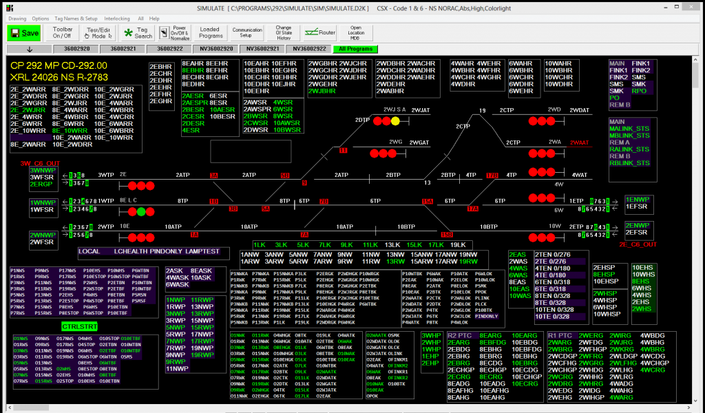
Vital-Sim provides a “Track Plan” window to allow a user to create schematic representation for a test location. A track plan is created by selecting, pasting and arranging items from an icon palette:
- Switches
- Color light signals
- Search light signals
- Position light signals
- Track segments
- Coded track segments
- Cab Signaling track segments
- Level Crossings
- Text/graphical elements
- Tag list boxes
Each icon is set-up/associated with user selected application inputs and outputs.
Once set-up, the track plan can be used as a user friendly interface for simulated location testing:
- Signal, switch position and blocking requests
- Train movements – shunting track segments
- Observer switch position, signal outputs
TRAINING WITH VSLS
VSLS can be useful for training junior circuit designers, designers unfamiliar with programming solid state interlocking devices, and personnel responsible for installation of the solid state interlocking devices.
The Simulator’s capability to display relay equivalents demonstrates logic formulas in graphic form. Because the display is active, it clearly shows how the signal circuit works. This feature is particularly helpful for Vital-Sim users. Personnel responsible for installation of the solid state interlocking devices are also able to train and review for the cutover by simulating the software in advance.
TESTING WITH VSLS
Proving out of relay-based interlocking systems, or revisions to such systems, can also be accomplished by writing equivalent logic formulas, compiling them with a vendor compiler of a choice, then running them on the VSLS. Toggling to the relay-equivalent display when a false response occurs enables the signal designer to see his mistake.
ADDITIONAL OPTIONS
Optional VSLS add-ons substantially reduce pre-cutover workload and assure the validity and completeness of cutover safety checks. The optional Lamp Out and Route Locking List Generators automatically provide cutover lists that have historically had to be manually generated by the designer producing the list.
The Route Locking List Generator additionally allows printing of pictorials of each route to assist with checking and analysis.